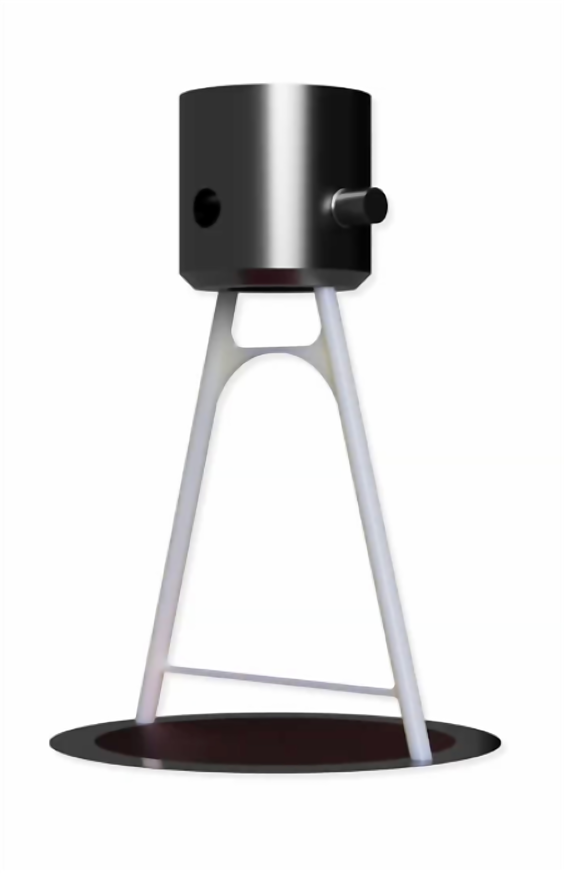
Goal & Constraints
Design a 3D-printed PLA component between a pin coupler and platen that holds ≥200 N in compression, deflects ≤10 mm, fits a tight envelope, and weighs as little as possible. Grade is a function of mass.
My Role
Full design — analytical modeling, FEA, and 3D-printed prototype.
Hand Calculations
FBD and force equilibrium for leg and crossbar loads. Legs carry combined axial compression + bending; the two crossbars are 2-force members (top compression, bottom tension). Crossbar height optimized to balance crossbar load against unbraced leg length for buckling. Hand calc peak stress 33.4 MPa.
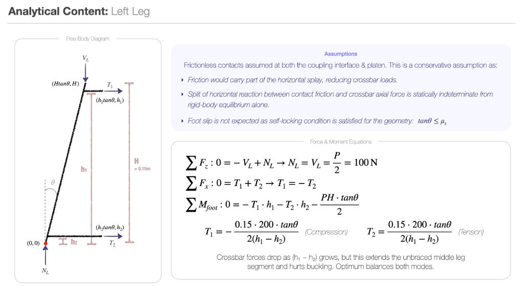
Analytical model — left leg FBD, force and moment equilibrium
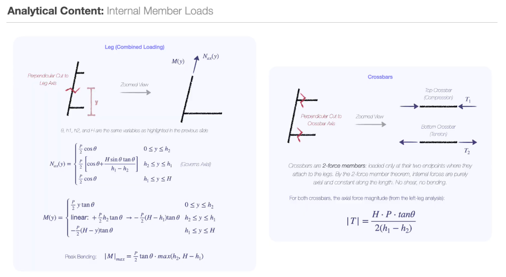
Internal member loads — axial N(y), bending M(y), crossbar 2-force analysis
Design & CAD
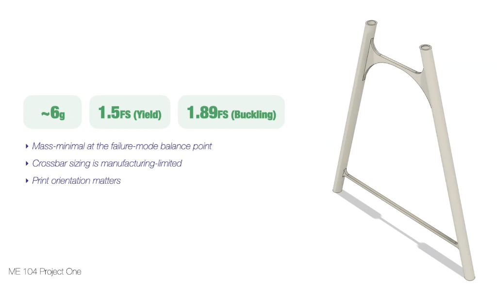
Final CAD — ~6 g, FS Yield 1.5, FS Buckling 1.89
A-frame topology converts the vertical load to axial compression in the legs and axial tension/compression in the crossbars, minimizing bending (PLA is weak in bending and interlaminar shear). Final: ~6 g, FS Yield 1.5, FS Buckling 1.89.
Build
3D-printed in PLA. Legs printed vertically to maximize axial strength.
Test & Results
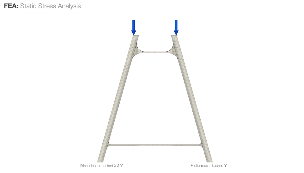
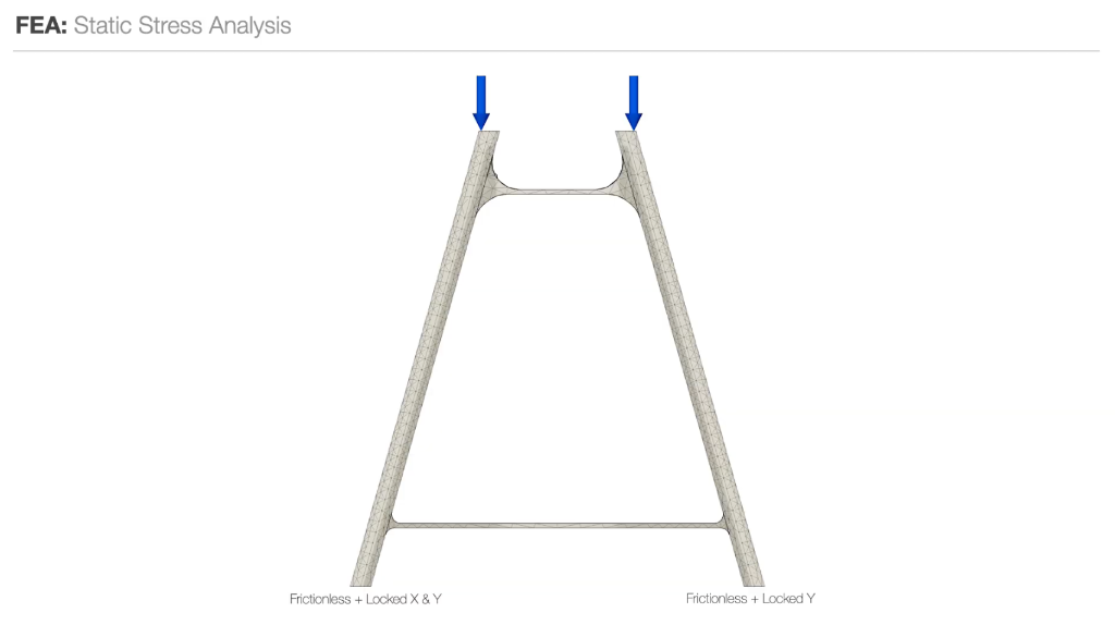
FEA stress setup — frictionless boundary conditions
Von Mises — peak 36.4 MPa at upper crossbar joint
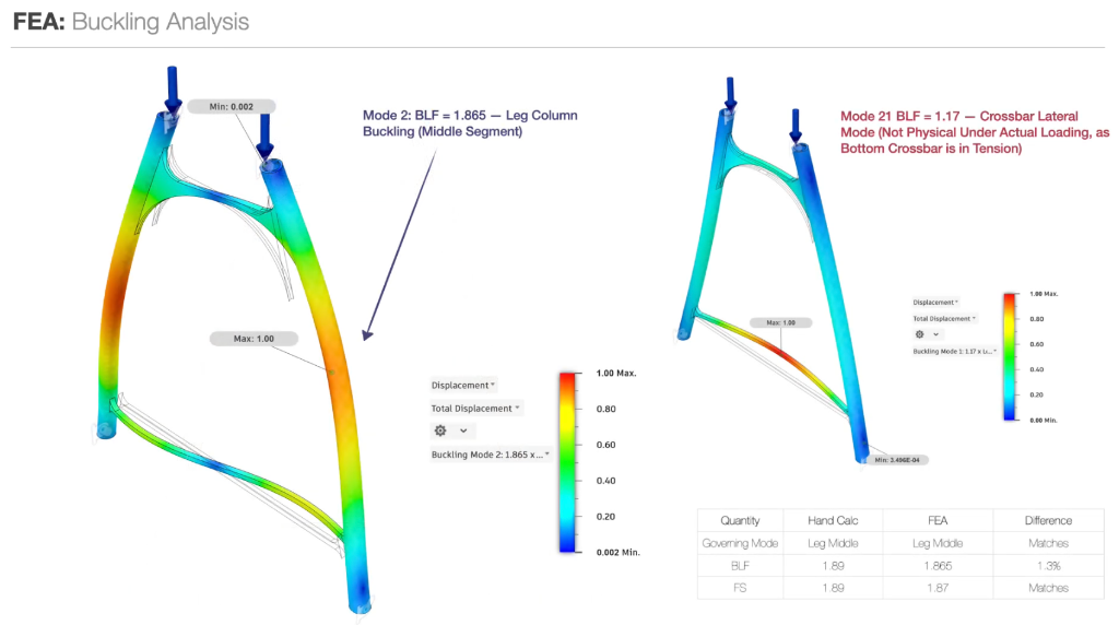
Buckling modes — Mode 2 BLF 1.865 (governing), Mode 21 BLF 1.17 (non-physical)
Static FEA: peak 36.4 MPa at upper crossbar joint vs 33.4 MPa hand calc (9% diff); yield FS 1.37 vs 1.50 target. Buckling FEA: BLF 1.865 (leg column) vs 1.89 hand calc (1.3% diff).
What Broke & What I Changed
Yield FS 1.37 came in below the 1.50 target at the upper crossbar joint — flagged as the design-limiting feature. Mode 21 (crossbar lateral, BLF 1.17) was non-physical under actual loading because the bottom crossbar is in tension.