Goal & Constraints
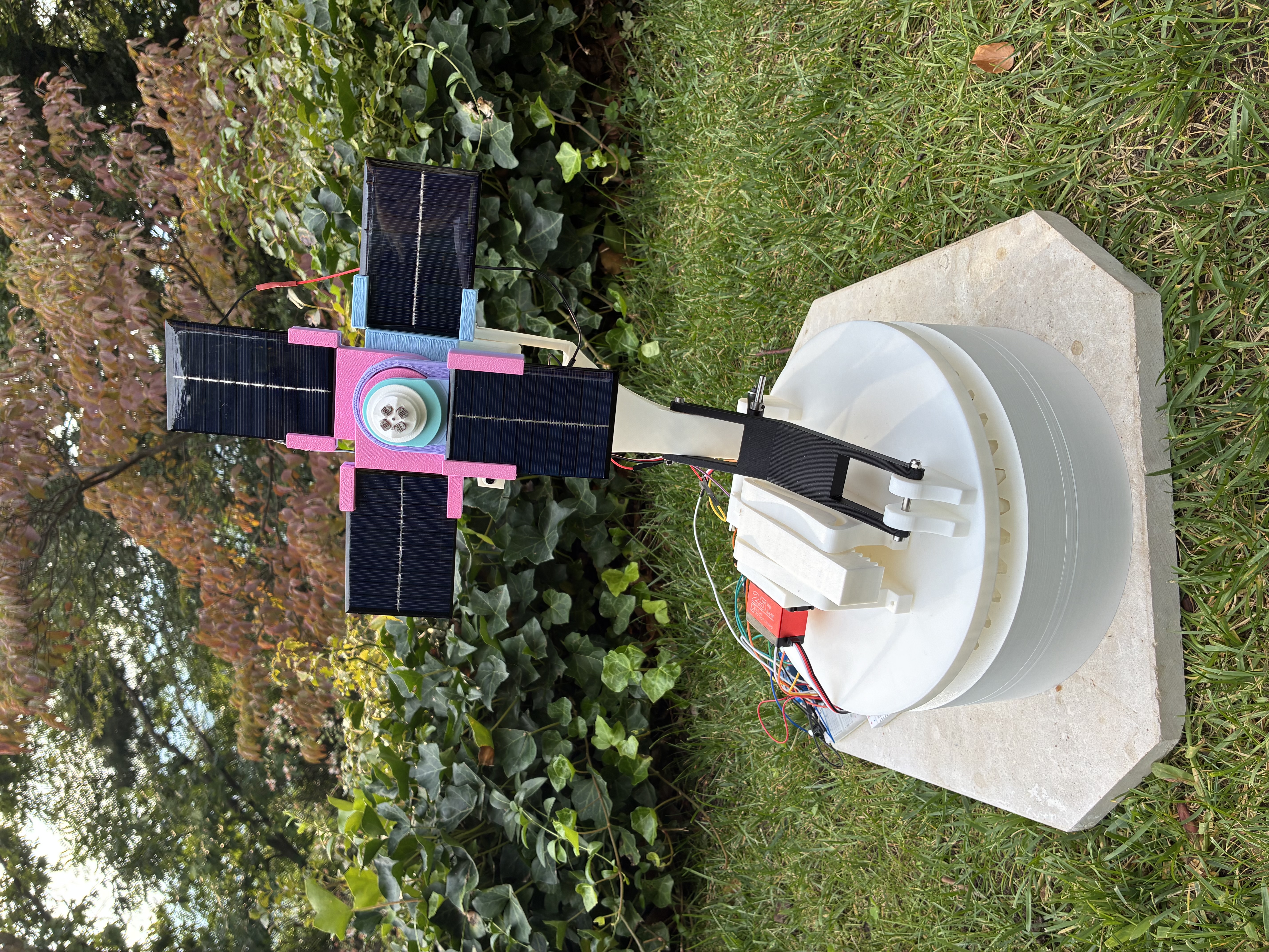
Portable dual-axis tracker keeping a 2.4 W array pointed at the strongest sunlight, sending power to a phone charger or onboard battery. • Array: 4 × 6 V panels, 2S2P — 12 V, 200 mA, 2.4 W • Storage: 7.4 V, 2200 mAh LiPo (16.3 Wh) • Sensing: 4 × LDRs; servos correct only when the array drifts off the strongest source • Dispatch: two paths — charge battery or power phone, no splitting array output • Key constraint: continuous servo holding could exceed the 2.4 W generated, so the tracker moves only on correction • Target: 14.6 Wh/day tracked vs 10.8 Wh/day fixed
My Role
Mechanical design, electrical design, and embedded control.
Hand Calculations
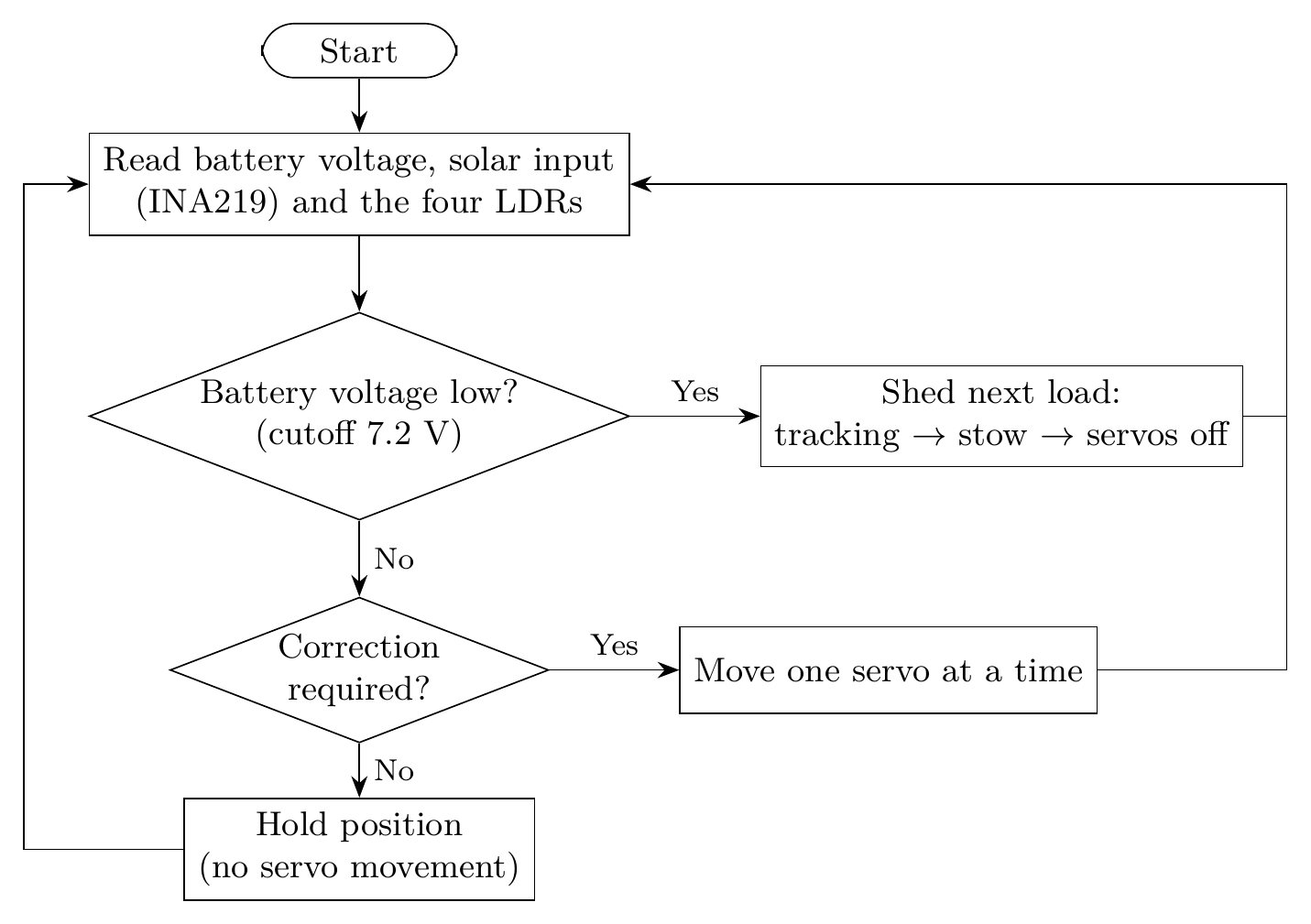
Fixed panel: P(θ) = Pmax·cos(θ). At 45° off-axis, output drops to 1.70 W. At 4.5 peak-sun-hours: • Fixed = 10.8 Wh/day • Tracked = 14.6 Wh/day • Overcast ≈ 2 Wh/day Control & Dispatch — Arduino monitors battery and solar input. As voltage falls, loads shed in sequence: • phone → tracking → retract • Cutoff at 7.2 V — above the 5 V converter's 6.5 V dropout and the BMS's 5–6 V disconnect • Letting the BMS shed would kill the controller with loads still connected and the structure deployed • Linkage sized to servo torque at minimum battery voltage, not datasheet max
Design & CAD
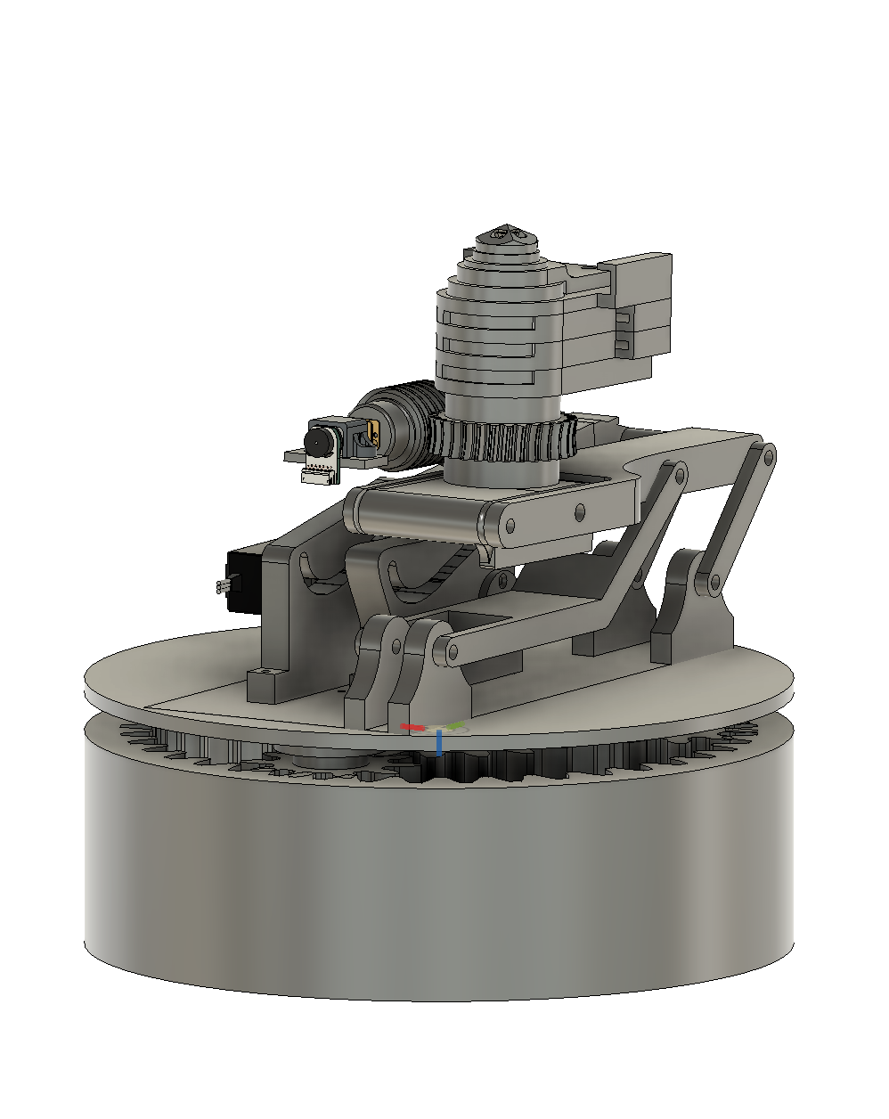
Full assembly CAD — base, azimuth drive, elevation linkage
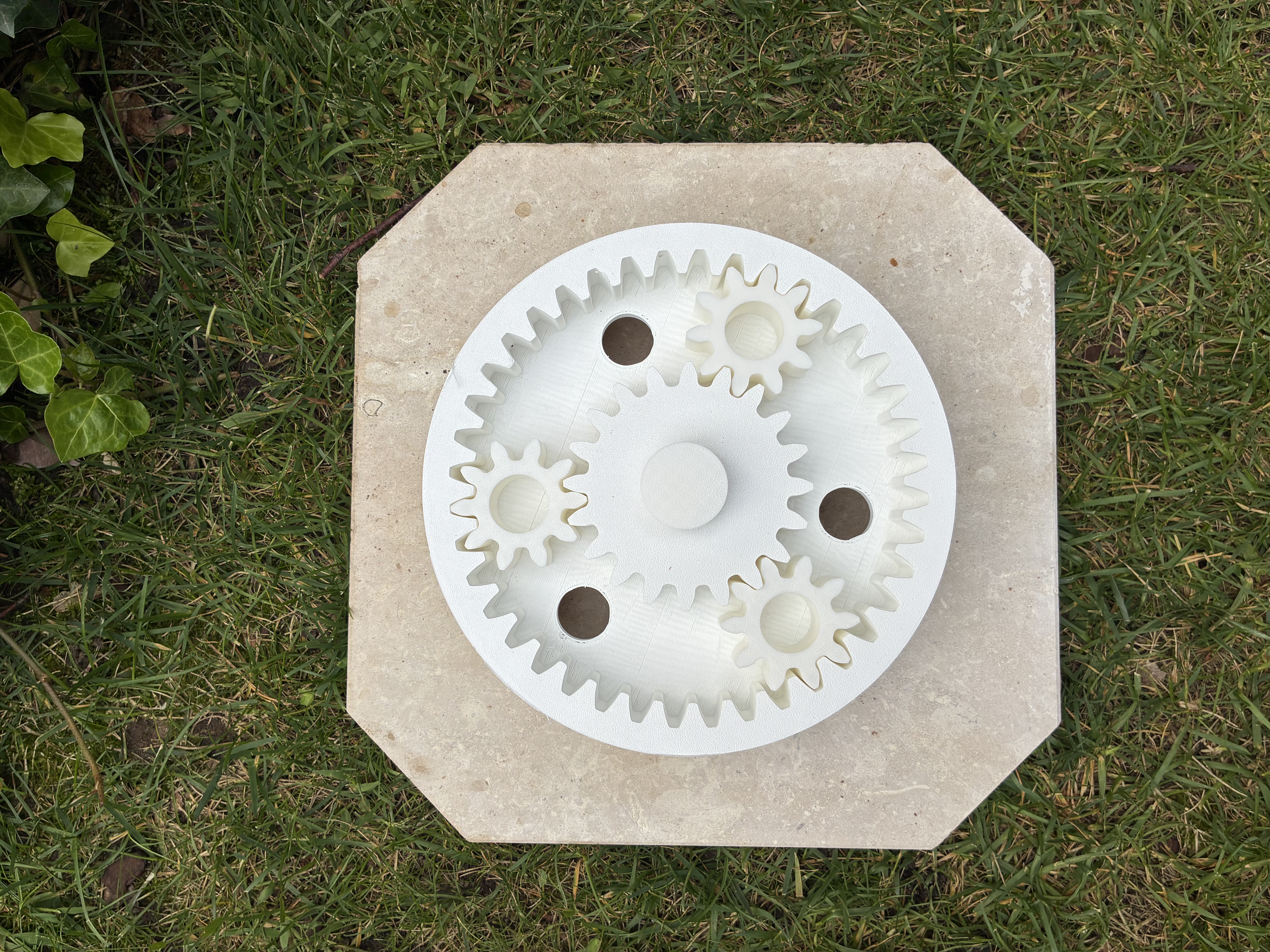
Planetary gearbox — azimuth drive
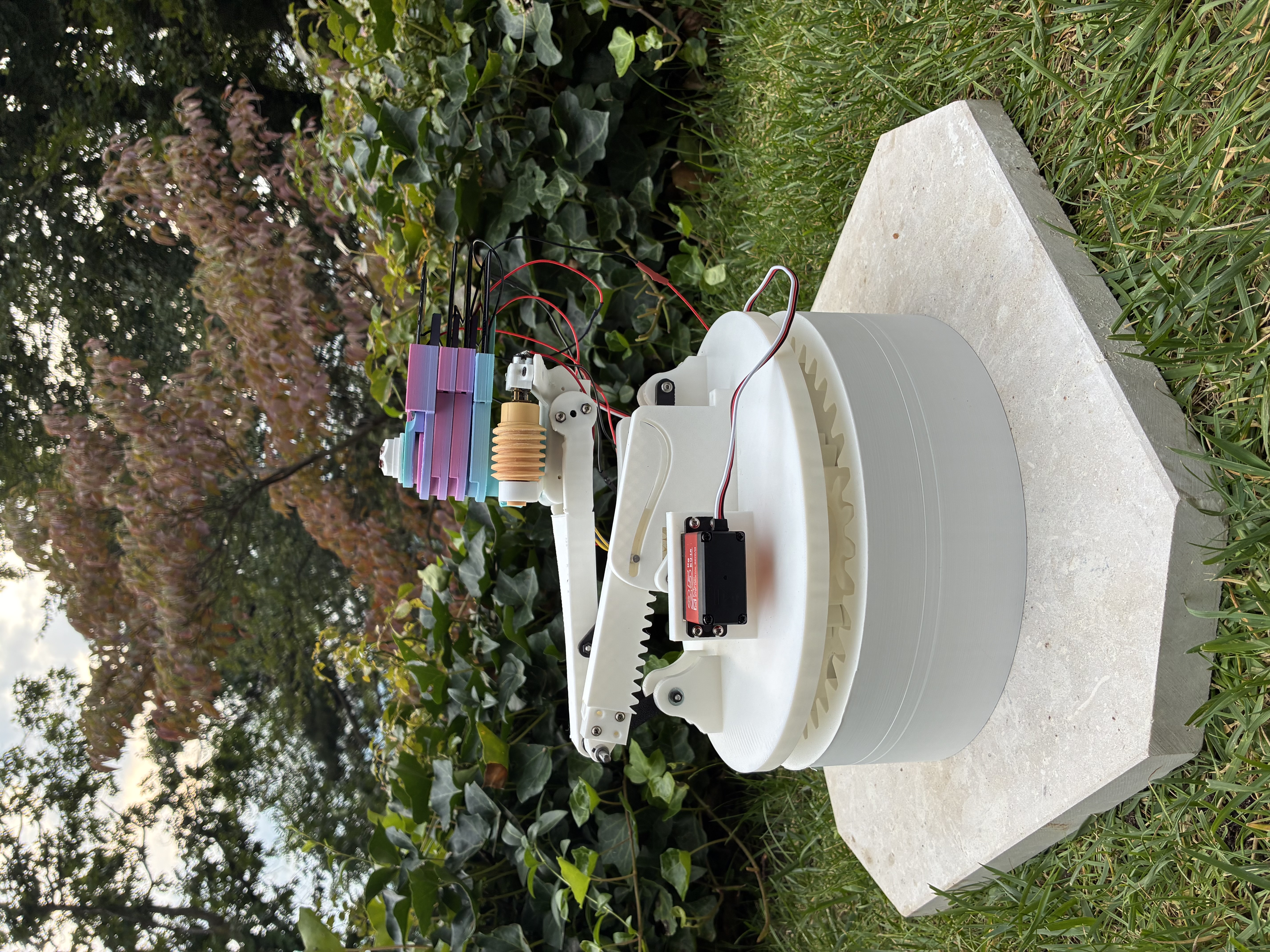
Folded: elevation arm lowered, rack-and-pinion retracted, panels stacked above the worm drive.
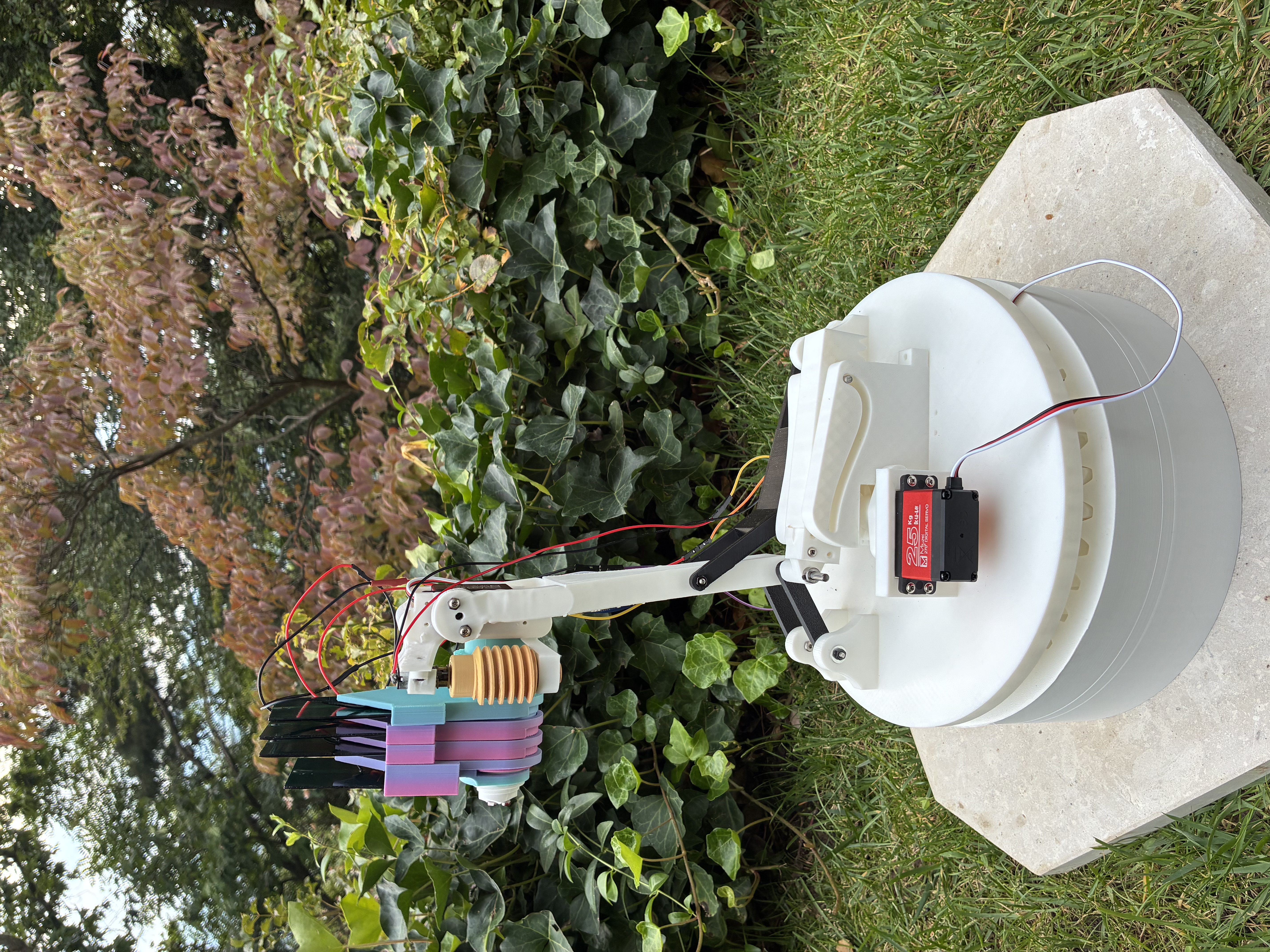
Elevation arm raised, panels still stacked.
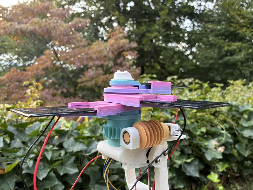
Panels deployed; the worm drive meshes with the gear that opens them. The four LDRs sit at the center.
Geared actuation for range at manageable torque: • Azimuth — planetary gearbox • Elevation — rack-and-pinion • Deployment — N20 gearmotor + self-locking worm drive (holds panels without continuous power) Tracking servos move only on correction, one at a time, to limit peak power.
Electrical Design
Solar array → INA219 → relay module → battery charger / phone
Battery → 5 V buck converter → Arduino + sensors
Battery → relay module → servos
Main Components
- Solar: 4 × 6 V, 100 mA panels, 2S2P
- Storage: 7.4 V, 2200 mAh LiPo + 2S BMS
- Charging: CC/CV buck converter, 8.1 V, ~0.2 A limit
- Control: Arduino Nano + 4 × LDRs
- Sensing: INA219 current/voltage sensor
- Actuation: 3 × high-torque servos + N20 gearmotor
- Switching: relay modules
- Regulation: 5 V buck converter
Charger is constant-current, not constant-voltage. A CV charger into a flat battery keeps ramping duty cycle to hit its target, drawing more than the panels can give and collapsing the array's output. The current limit stops this. 2S2P (12 V) vs 4S (24 V) halves array voltage, cutting conversion loss — and isolates shading between panel pairs. Panel wiring | Array voltage | Battery charging | Phone output 4S | 24 V | ~80% | ~70% 2S2P (used) | 12 V | ~88% | ~82%
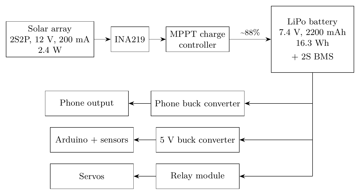
Power flow diagram
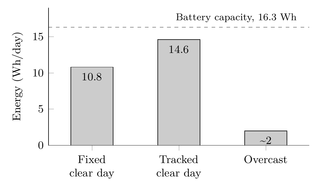
Daily energy — fixed vs tracked vs overcast
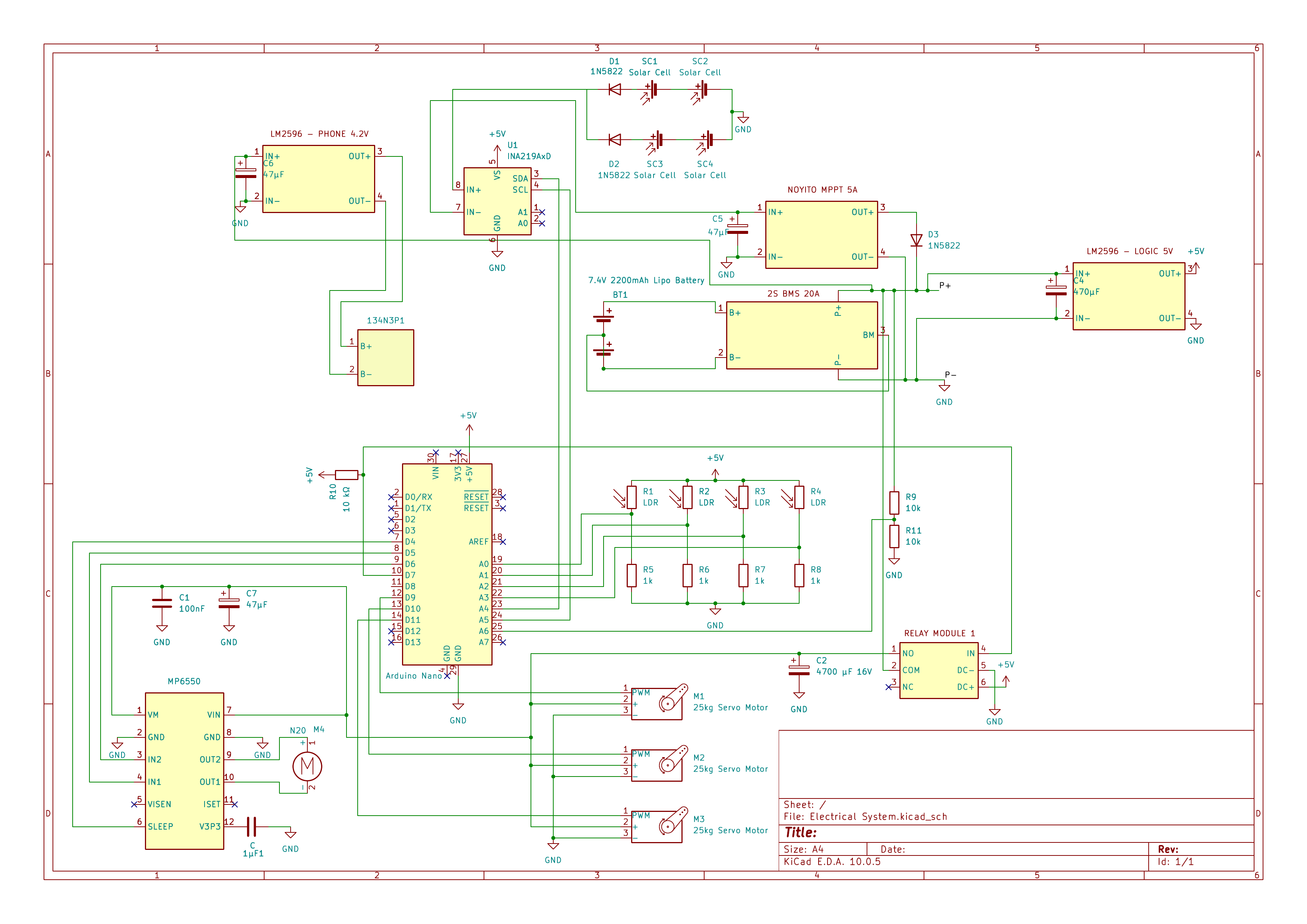
Full electrical circuit — KiCad schematic
Deployed array — four panels tracking
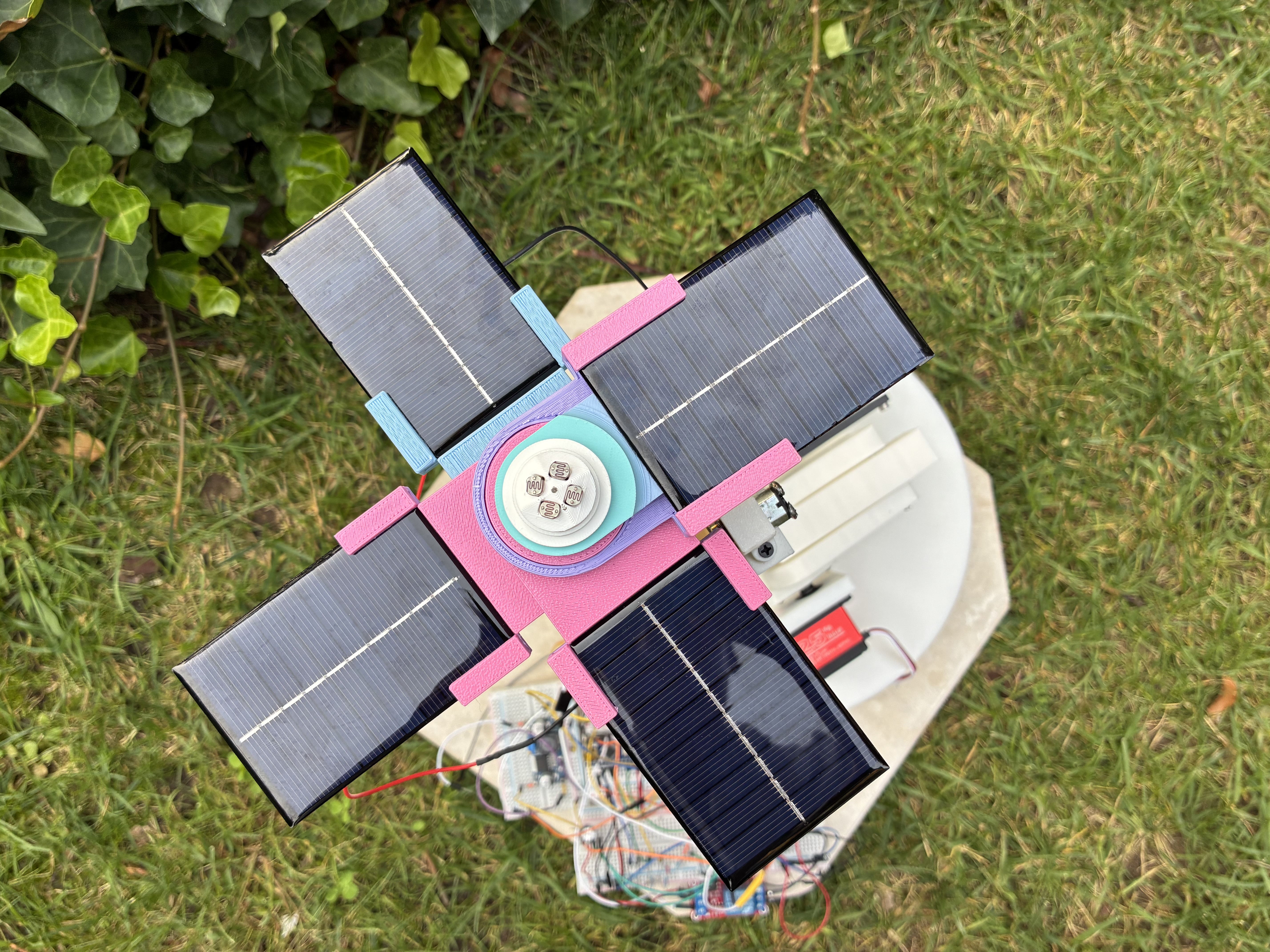
Deployed array — four panels tracking
Scaling Up
Same problem as grid-scale solar: capture → store → dispatch. Solar peaks at midday; demand runs into the evening. Texas 2024 summer peak: ~86 GW late afternoon, but the net peak came later once solar dropped. Grid batteries close that gap. At scale, architecture moves from LiPo/relays/LDR feedback toward: • MPPT • High-power converters • Thermal management • Advanced BMS • Modular long-duration storage (DOE: ≥10 hours) Single-axis is often preferred at scale — most of the gain, less complexity. Dual-axis wins when maximizing energy from limited area outweighs complexity. Same tradeoff here: bigger actuators support bigger panels but draw more power; stronger structures handle more load but add weight.
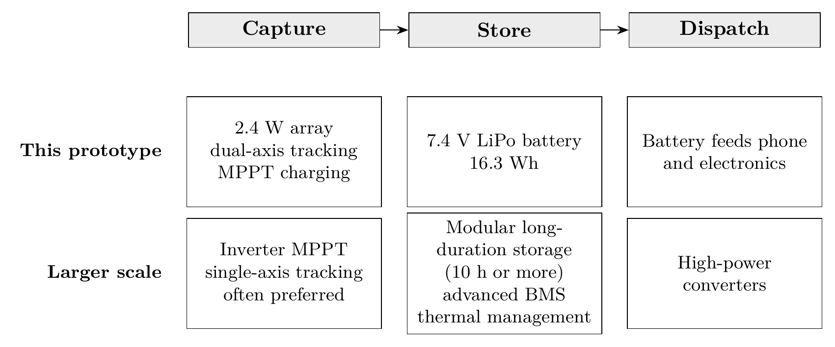
Scaling architecture — capture, store, dispatch