Goal & Constraints
Build a small, low-cost wind tunnel to test small models of the aerobodies we are surface modeling for the Stanford Solar Car Project, and see if there is any obvious flow separation.
My Role
Full design and fabrication — thermal and aerodynamic sizing, laser cutting, and assembly.
Hand Calculations
Component sizing was driven by the fan's estimated airspeed and the straw dimensions for the flow straighteners. The fan runs 750 CFM at a 20 cm diameter. We skipped a diffuser for time and material constraints, so the fan sits at the end of the test section. Setting chamber — 40 × 40 cm: 750 ft³/min = 21.24 m³/min = 0.3539 m³/s V = Q/A = 0.3539 m³/s ÷ 0.16 m² = 2.21 m/s Straws — 3 mm diameter, 12.7 cm long. The gap between the two acrylic straighteners was set slightly shorter so the straws would fit: A_straw = π(d/2)² = 7.07 × 10⁻⁶ m² N_straws = 0.16 m² ÷ 7.07 × 10⁻⁶ m² ≈ 22,623 straws V_straws = 0.3539 ÷ (22,623 × 7.07 × 10⁻⁶) = 2.21 m/s Test section — 20.3 × 20.3 cm at ~6 m/s (assuming a 30% loss factor): Q_actual = 0.3539 × 0.7 = 0.248 m³/s A_test = 0.248 ÷ 6 = 413 cm² Length = 4 × 413 ÷ (4 × 20.3) ≈ 413 cm² → × 3 = 61 cm (optimal length is 3–5× the hydraulic diameter) Contraction: A_in = 0.16 m², A_out = 0.04 m² Contraction ratio = 4 L_contraction = 0.5 m
Design & CAD
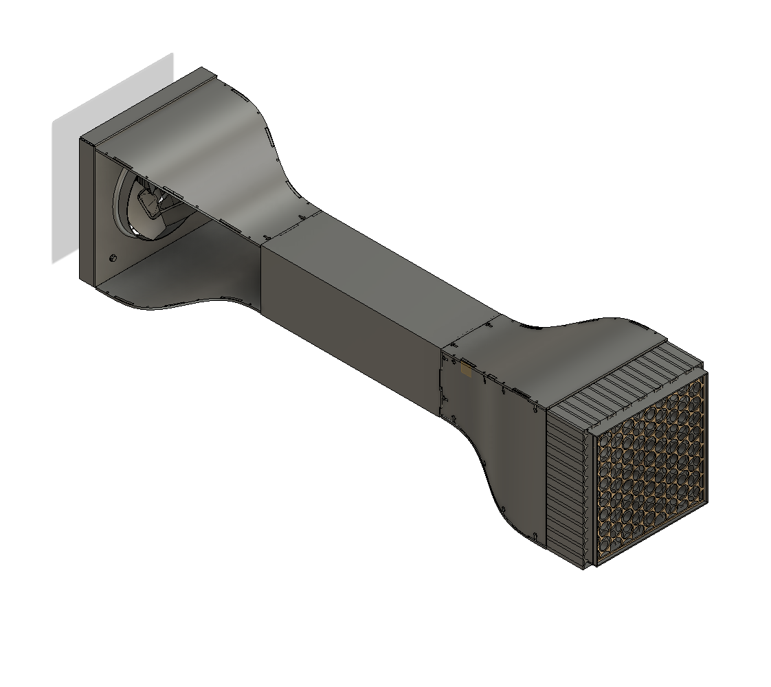
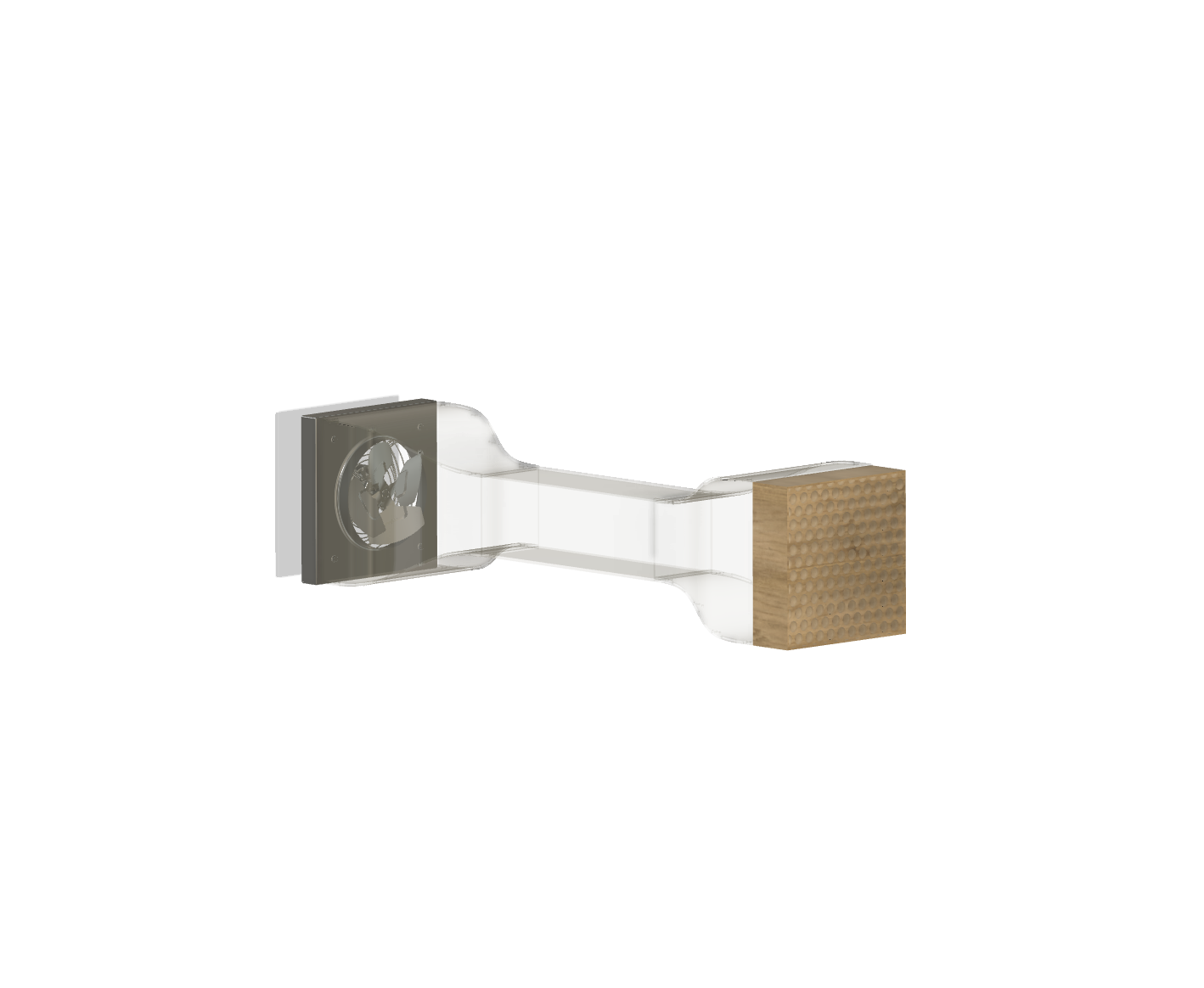
CAD model — fan housing, contraction, test section, honeycomb straightener
Initial sketch: fan, a wall of flow straighteners, mesh screen, contraction zone, test section, and a diffuser. After testing the fan we bought, we turned it around to suck air for a steadier flow — so the final order became flow straighteners, mesh, contraction, test section, then fan at the end. CAD model of the assembled tunnel: fan housing and inlet on the left, smooth contraction, test section, and the honeycomb flow straightener on the right.
Build
We laser cut every component from wood and acrylic — the precise way to cut the materials. We originally planned an all-acrylic tunnel, but switched to wood because it was far cheaper; it was unnecessary to use acrylic throughout since only one wall of the test section needed to be clear. All components were connected with duct tape at the end.
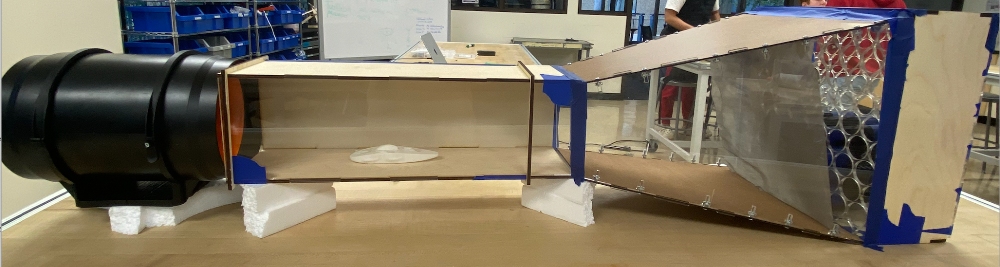
Assembled tunnel — fan, test section, contraction, flow straighteners
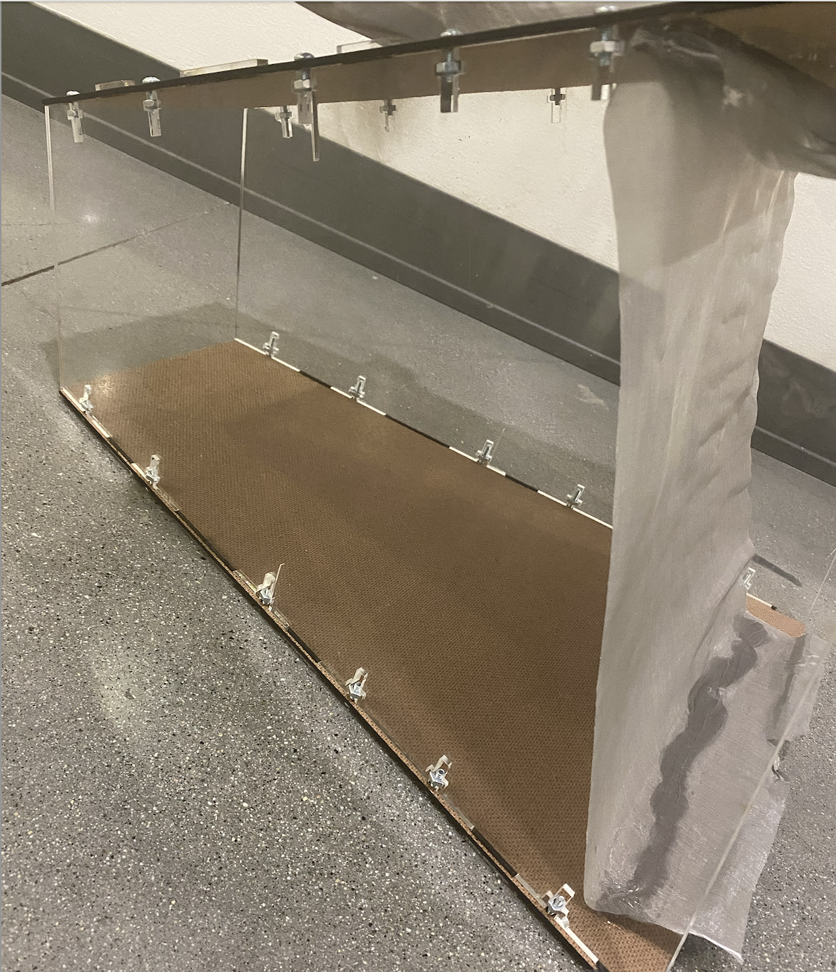
Contraction zone — acrylic walls, mesh screen added at the inlet
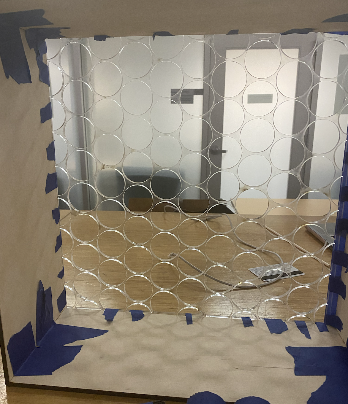
Flow straightener — laser-cut acrylic holding the straw grid
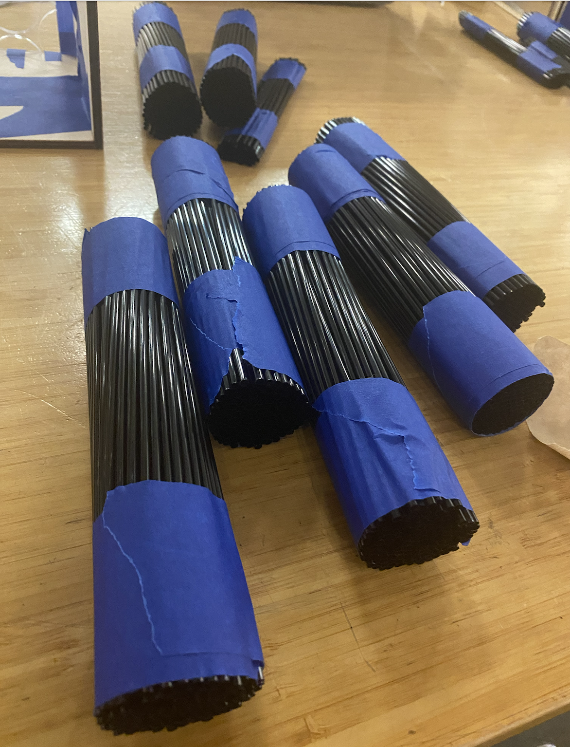
Straw bundles — wrapped in duct tape before feeding through the acrylic
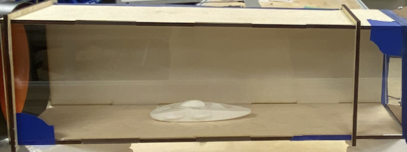
Test section — clear acrylic wall, 3D-printed aerobody centered on the floor
Test & Results
The first test ran in class and overall it worked — we could see flow over the car. But we knew we were losing airspeed because the fan didn't perfectly fit the test section and the test section had no top wall.
What Broke & What I Changed
Bending acrylic was the major challenge. We originally wanted the contraction walls to curve inward rather than slope, and spent an hour trying to bend a thick piece into the right shape. Bending 1/8 in acrylic wasn't hard, but we could only heat a small section at a time, and getting the exact shape by hand without molds was the hard part. We decided four identical hand-bent panels weren't possible, so we laser cut the walls instead. We also came up severely short on straws — despite calculating the count and buying enough — so we placed the straws in the lower middle of the straighteners, facing where the car sits.
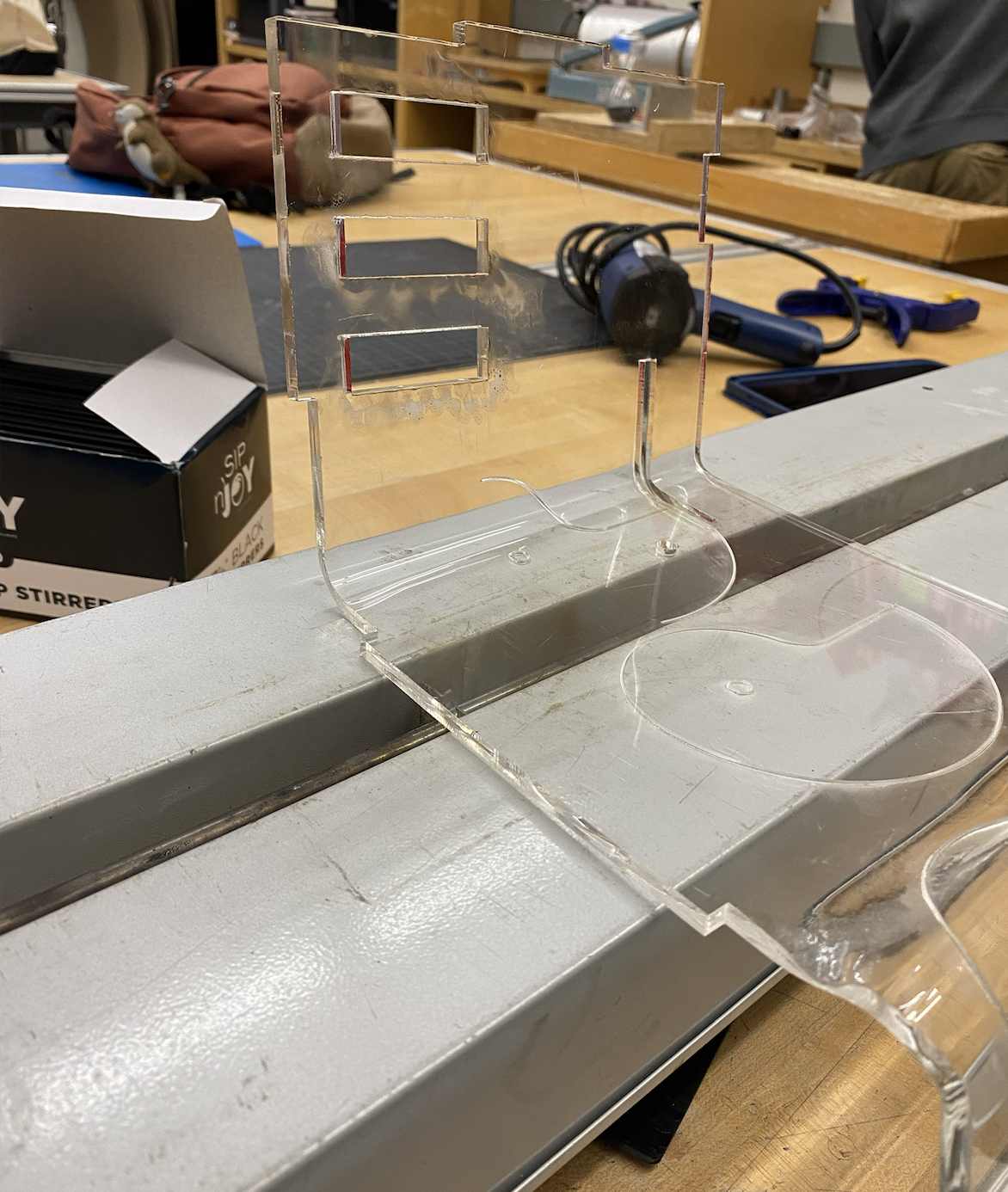
Acrylic bending attempt